
A successful import is only the first check
A building information modelling (BIM) exchange is successful when the receiving team can use the required geometry and data for its agreed task. Opening the file without an error does not demonstrate correct positioning, classifications or properties, or show which source revision produced it.
Set the exchange purpose before selecting settings. Viewing, coordination, quantity extraction and further editing need different information. Industry Foundation Classes (IFC) is a building information exchange standard; using it does not guarantee that every native feature or application behaviour will survive conversion.
Record the exchange configuration
Keep the source application and version, exporter version, format or schema, export settings and reference revision with the delivery record. Record the receiving application and relevant import settings as well. This makes a failure reproducible and prevents two teams from comparing files created under different conditions.
Autodesk's Revit 2026 IFC linking guidance includes class mapping, positioning choices and an intermediate model generated during linking [1]. This illustrates why the actual import workflow matters. It is not a universal instruction to use one positioning option for every exchange.
Check location before detailed coordination
Agree reference points and levels that both teams can identify. Check position, orientation, elevation and units in the receiving environment. Use more than one known reference so an apparently correct point does not conceal a rotation or scale problem.
If alignment fails, investigate the source and receiving settings before manually moving the imported model. A local adjustment may make one review look correct while breaking the next update. Record any justified transformation and ensure that it can be repeated and understood by recipients.
Check meaning as well as shape
Inspect representative elements for their classification, system assignment, required properties, data types and units, including unusual objects. A sample tests the method, not the completeness of the entire exchange. Add checks across the agreed scope for required objects and data. Test whether element references remain usable after an update; do not assume identifiers remain unchanged through every export.
buildingSMART's Information Delivery Specification (IDS) can express selected IFC data requirements for checking, but does not cover geometry [2]. Use separate positional and geometry checks. A passing property report should not hide missing objects, changed boundaries or unusable shapes.
Reconcile omissions and exclusions
Record intentionally excluded elements and explain how they affect the exchange purpose. Compare relevant quantities or element sets using defined inclusion rules, not unexplained totals. A difference may arise from linked models, export filters or representation choices rather than an authoring error.
An illustrative issue is a maintainable item that appears visually but lacks the agreed asset identifier. It may be adequate for a spatial review and unsuitable for an asset data import. The correct response depends on the intended use, so the exchange report should state the restriction instead of calling the whole file good or bad.
Tekla to Revit: a steel factory model
A steel factory model supplied in Tekla Structures may contain fabrication-level members, connections and assemblies. Bringing that model into Revit is not simply moving a picture: the receiving team may need a coordination reference, building documentation or editable content. Trimble describes different exchange workflows, including geometry-only outputs whose organisation may not meet Revit drawing requirements [3].
The practical challenge is retaining the steelwork's intended geometry and useful identity without implying that every fabrication feature becomes a native Revit object. SBT's digital delivery support can help define and organise the receiving content around the project's actual use, rather than treating a file that opens as a finished conversion.
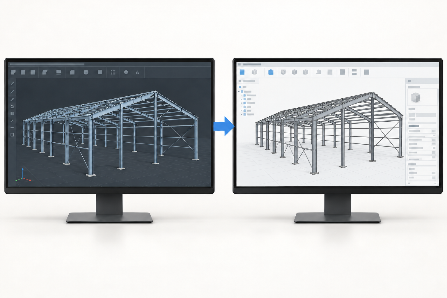
Plant 3D to Revit: process equipment and its interfaces
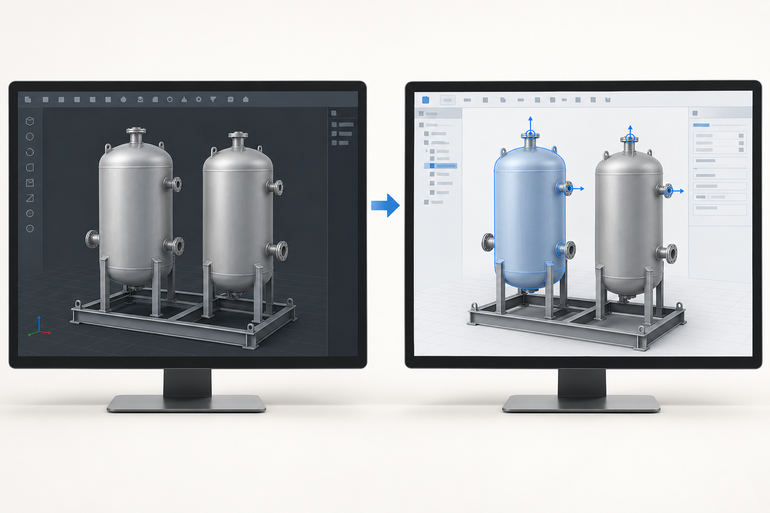
A process tank can have a clear physical shape while still lacking the information required by a building-services model. Plant 3D objects and Revit elements use different representations; Autodesk documents why application-specific DWG objects may not display correctly in a direct Revit link [4].
For a tank with nozzles, the useful result is not only a recognisable vessel. Where required, the receiving Revit content also needs defined connection locations and the appropriate connector information. The illustration distinguishes the supplier's physical nozzle from a receiving BIM connection definition. These connectors require deliberate content adaptation and suitable engineering information; they are not automatically created by geometry conversion.
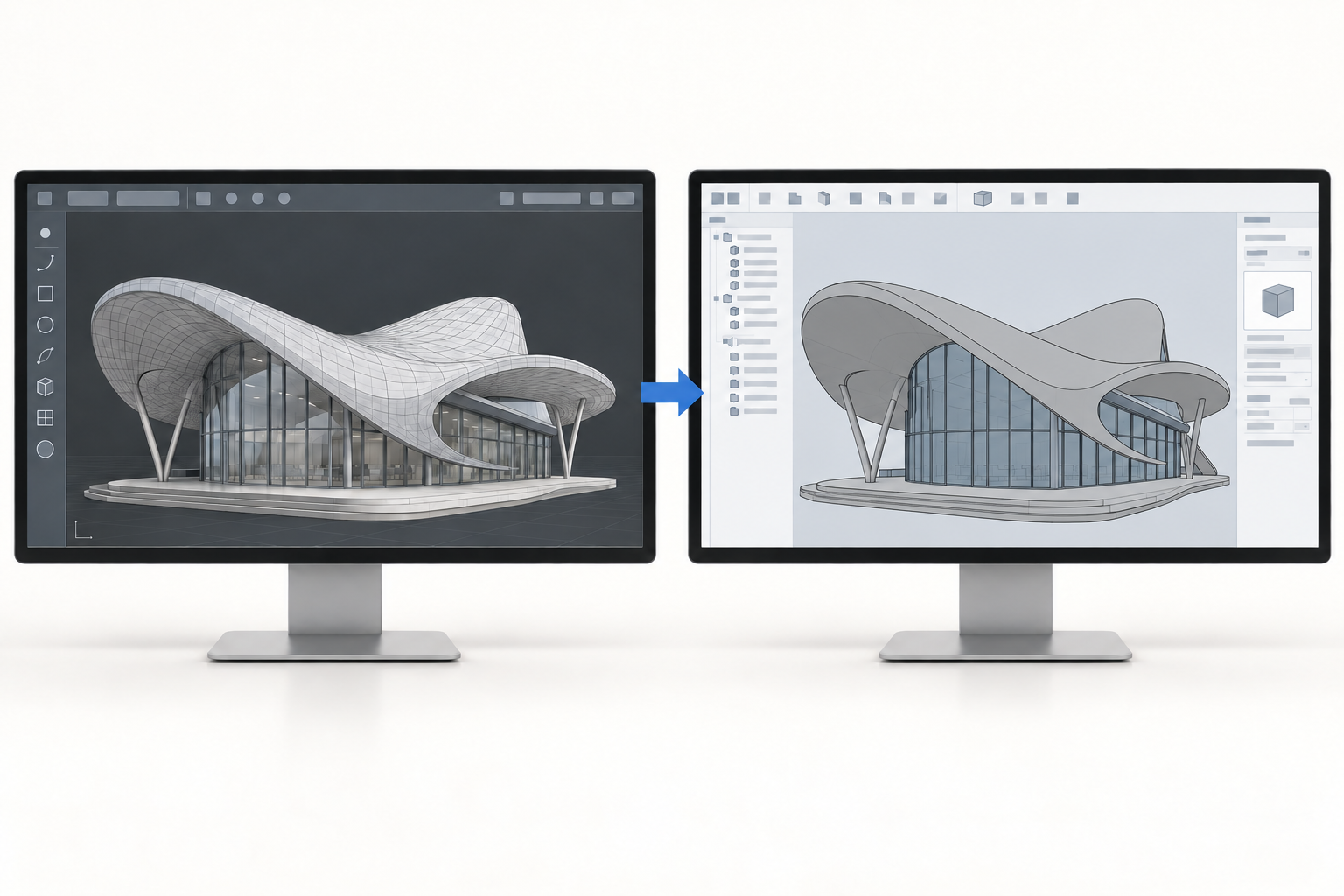
Rhino to Revit: preserving a freeform building
A building developed in Rhino may use curved roofs and freeform surfaces that do not correspond directly to standard Revit walls or roofs. The challenge is preserving the design while deciding what the receiving model needs to represent. McNeel describes Rhino.Inside.Revit as a bridge between freeform modelling and BIM, with tools that can create native Revit elements [7]. This does not mean that any complex surface automatically becomes a fully parametric building element.
The appropriate level of adaptation depends on the task: design coordination may need the faithful overall form, whereas documentation and further development may need more structured building content. SBT's model-delivery support can help organise that distinction so a visually accurate import is not mistaken for a complete authoring model.
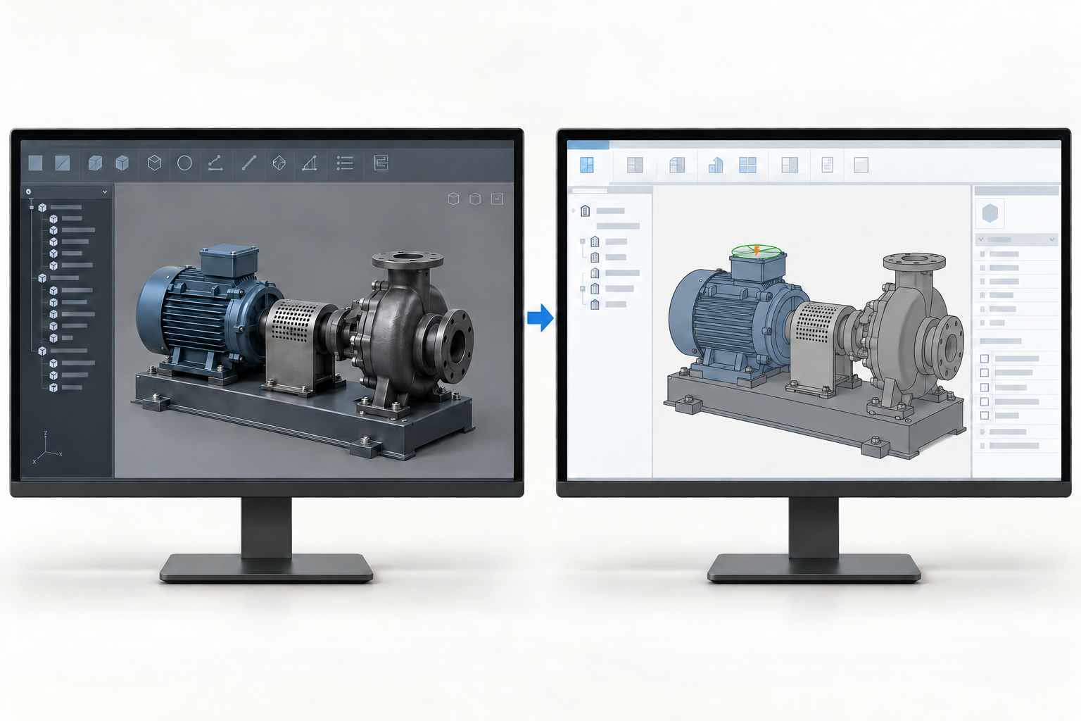
SOLIDWORKS to Revit: making mechanical equipment usable
A mechanical equipment assembly may include detailed manufacturing parts that add little value to building coordination. Autodesk documents an Inventor-based interoperability path for SOLIDWORKS content and simplified RVT output [5][6]. The receiving requirement should drive the level of detail, not the volume of geometry available.
For an electrically driven pump set, useful Revit content may need the equipment envelope, identity and an electrical connector at the appropriate terminal location. A connector is a BIM definition, not merely a visible point or wire. Its category, connection information and electrical characteristics must be adapted from suitable supplier and project data; they should not be invented from the shape. SBT can support the organisation of equipment content for digital delivery without presenting a raw manufacturing import as a ready-to-use family.
Bridging manufacturing and construction
These four examples are starting points, not the limits of model exchange. Manufacturing and construction describe different aspects of the same physical assets: one develops how a component is made, while the other needs to understand where it fits, how it connects and how it will be installed and maintained. Their digital information should support that connection rather than become an avoidable barrier.
The difficulty often lies between a detailed supplier model and the building model that a project team can actually use. A component may look correct but still lack useful identity, suitable geometry or the connection information needed by the receiving workflow. Recreating content or resolving these gaps late can add repeated work and leave manufacturing and construction teams working from disconnected information.
SBT provides cross-platform model conversion and BIM-content adaptation support to help bridge this gap. The aim is to carry useful design and equipment information between manufacturing and construction environments, and to organise it for the receiving team's purpose—not merely to change a file extension. The direction of exchange, retained information and required adaptation depend on the source content and target platform; there is no blanket promise of lossless, fully editable conversion in both directions.
Keep a repeatable acceptance sample
- Reference position, orientation, levels and units have been checked.
- Required systems and representative element types are present.
- Required properties retain their intended names, values and units.
- Element identity and update behaviour support the receiving workflow.
- Exclusions and conversion warnings have been reviewed.
- The delivery can be traced to its source and exchange settings.
Retain the test results and rerun the relevant checks when the toolchain or settings change. SmartBuild Tech's digital delivery support can help define this receiving test, rather than leaving interoperability to an unverified assumption.
References
- Autodesk Revit 2026 Link an IFC File ↗ Import mapping, positioning and intermediate files. Accessed 3 October 2026.
- buildingSMART International Information Delivery Specification ↗ Information requirements and the limits of IDS checking. Accessed 3 October 2026.
- Trimble — Tekla Structures & Revit BIM workflows ↗. Exchange routes and geometry-only limitations. Accessed 3 October 2026.
- Autodesk — Exporting and Importing models with AutoCAD Plant 3D and Revit ↗. Object Enabler limitations and ACIS geometry exchange. Accessed 3 October 2026.
- Autodesk Inventor 2026 — To Import Files as an AnyCAD Reference or Convert Model ↗. Supported source formats and import choices. Accessed 3 October 2026.
- Autodesk Inventor 2025 — To Export a Model to RVT (Revit format) ↗. Simplification and RVT output; verify settings for the installed version. Accessed 3 October 2026.
- McNeel — Rhino.Inside.Revit ↗. Freeform-to-BIM integration and native element capabilities. Accessed 3 October 2026.
Useful insight?